 |
Главная |
BENDING: STRESS AND DEFORMATION
|
из
5.00
|
 Tensile bending stress is at a maximum in the outer layers of the beam. The smaller the moment of inertia Ixx, the larger the maximum bending stress. Shear stress is equal to zero at the outer layers. It is at a maximum on the neutral axis of the beam. Tensile bending stress is equal to zero at the neutral axis.
 The deflection is proportional to force and length3. This means that a doubled length increase deflection by 8 times.
For a distributed load the order for length is higher.
 Deflection and rotation in the center can affect deflection of the right end of the cantilever beam.
Heating of the upper flange of the cantilever beam causes thermal expansion of upper layers and changes the beam shape.
 The shape of the flexible beam depends on the external moments at the beam ends Mi = Fi hi.
MIXED MODE LOADING
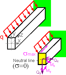 If an external force passes through the center of the cross-section for the shown scheme there is no torque Mz=0 and no projection of inner forces at axis z: Pz=0.
Upper layers of the cantilever beam are under tension and lower layers are under compression. If forces don't lie in a plane with a principle axis, the neutral axis swings through some angle. The stress is highest in points that are furthest from the shown neutral axis. The top left point of the section has the maximum tensile stress.
 The summed stress pattern can be obtained by considering the tension and bending of the beam. For long cantilever beams bending stress is usually higher than tensile stress if both forces are equal.
 If a compressive force was applied outside the center of the cross-section, a tensile bending stress may occur. There is an area in which the addition of a compressive force does not cause tensile stress in the column. The shape of the zone for cylindrical sections is a circle.
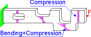 If the line of force application and the center of the cross section do not coincide by a distance h, there is bending moment F*h that causes compressive and tensile stresses.
 Additional bending moments cause a change in the shape. The shape depends on the sign of the bending moment, positive or negative.
 The principle stress is at a maximum in the embedded end of the structure, where torque T and bending moment M are highest.
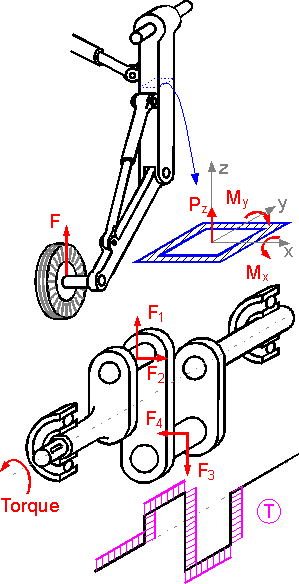 Force and moment diagrams for a complex structure can be obtained by the static equilibrium conditions. Maximum number of inner forces and moments is 6. There are geometries where less than 6 components of inner forces and moments act.
BUCKLING
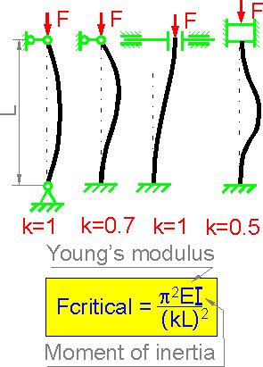 In 1757, Leonard Euler proposed a relationship for the critical load that would produce buckling in a pinned-pinned column. For other supporting schemes (fixed-pinned, fixed-fixed, fixed-free, etc.) engineers use an effective length Le = k*L where k is the effective length constant.
 The numbers show percents of critical buckling force for each column in comparison with the uniform column. The last case demonstrates the most efficient use of the material.
 There are two extreme directions with maximum and minimum values of the moment of inertia. The buckling occurs in the direction of the minimum moment of inertia.
For a rectangular section buckling occurs perpendicular to the longer side. The resulting deformed shape of the column depends on how the column is supported.
 The calculation shows that the critical force is the highest for a structure with maximum shear rigidity. This condition corresponds to an optimal angle 35.26 degrees. For smaller or larger angles the shear stiffness is smaller.
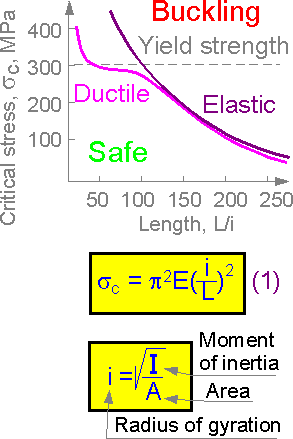 The critical stress corresponding to buckling depends on beam length and yield properties of the material. In short columns the critical stress can exceed the yield strength (tension).
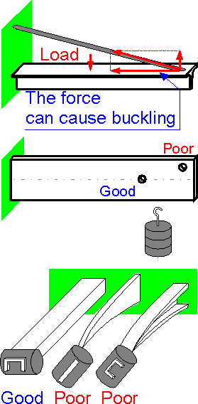 A tensile force in the cable compresses the beam. The loading can result in buckling of the beam.
The closer to the fixed end, the smaller the bending moment. The closer to the neutral axis, the smaller the torque under buckling.
The first example of the cantilever beams demonstrates the most efficient use of the material. The last two structures are unstable due to possible buckling and torsion.
|
из
5.00
|
Обсуждение в статье: BENDING: STRESS AND DEFORMATION |
|
Обсуждений еще не было, будьте первым... ↓↓↓ |

Почему 1285321 студент выбрали МегаОбучалку...
Система поиска информации
Мобильная версия сайта
Удобная навигация
Нет шокирующей рекламы

