 |
Главная |
THREE-DIMENSIONAL STRUCTURES
|
из
5.00
|
 For three-dimensional structures there are six components of moments and forces in a point. If we cut the curved beam perpendicular to the beam axis the torque is equal to the product of Force by Arm : F*r1 and the bending moment is equal to F*r2. Internal forces are equal to the sum of corresponding projections of external forces.
 The figure shows examples of bending moment and torque diagrams for three-dimensional structures. The diagrams are built by the above-mentioned rules.
 There are tensile as well as compressive stresses at external surface of the arc. The bending moment changes its sign.
 For a thin-walled sphere, absolute value of radial stress at the external surface is equal to external pressure. It is smaller than meridian and tangential stress components.
 The first step of the analysis includes determination of reactions in the supports. There is symmetry in the structure. There are no torque or bending moments in part of the structure.
The conclusion is purely theoretical, the structure is not stable. Loss of stability causes additional forces and moments for all parts of the structure.
REFERENCES
M. Gere, S.P.Timoshenko Mechanics of Materials, 4th edition, Pws Pub Co, 1997.
F. B. Seely, Advanced Mechanics of Materials, John Wiley and Sons, Inc., New York, 1952.
L. Spiegel, G. Limbrunner Applied Statics and Strength of Materials, 3rd edition, Prentice-Hall Career & Technology, 1999.
S. Timoshenko Strength of Materials, Part I & II, Van Nostrand Company, Princeton, N. J., 1956.
THEMES
Theme 1. Stress Concentration
Theme 2. Fracure Mechanics
Theme 3. Mechanical Properties
Theme 4. Strength of Materials
Theme 5. Theory of Elasticity
Theme 6. Structural Safety
Theme 7. Material Science
Theme 8. Welds
Theme 9.Composite Materials
Theme 10. Finite Element Analysis
THEORY OF ELASTICITY
Igor Kokcharov and Igor Zyryanov
DEFORMATION
 An elastic body can be shifted and extended. Analysis of the displacements u, v and w shows whether there is deformation or not. Change of the element sizes and its shape can be characterized by deformation, difference in displacements, or by strain. Strain is the deformation of an element divided by the original length of the element. There are 6 components of strain. There is linear strain ei and shear strain gij . The strain ex is the derivative of displacement u with respect to coordinate x. Definitions for the other strain components are shown in the figure.
Volume expansion e depends on linear components of strain only. Shear strain gxy has no affect on the parameter.
 The strain components change if the axes is rotated by angle q. According to the second formula shown at the right, shear strain gxy = 0 if all three linear components of strain are equal.
 In an elastic body strains cannot be chosen arbitrarily, they must satisfy to the strain compatibility equations.
 For plane strain there are two axes along which the linear strains are at a maximum. The axes are called principle axes. Angle q defines their position. The expressions are given for maximum linear strains e1, e2 (plane problem) and maximum shear strain gmax (three-dimensional problem).
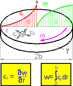 The radial displacement w is smaller in the center of rotating disk. The displacement is a result of summation under the shown curve of radial strain er. The larger radial strain and gradient of the displacement are observed in the central part of the disk.
STRESS
 Stress is the intensity of an internal force acting on a point in an object. Stress is measured in units of force per area. Axial (or normal) stress (s) is defined as the force perpendicular to the cross sectional area of the body divided by the cross sectional area. Shear stress (t) acts parallel to an imaginary plane cut through an object.
Centrifugal forces act to move an elementary ring from center. The elementary ring is extended. Both shown stress components, radial and tangential, are positive.
 There are 9 stress components at any point.
The condition for zero rotation of the element, found by taking moments about the axes through the center of the cube parallel to the coordinate axes, reduces the number of independent components to six.
Six stress components are enough to describe any state of stress in a point.
 The equilibrium equations must be satisfied for an elastic body. Mass is not considered in the equations. The shown stress components correspond to three-point bending and satisfy the equilibrium equations.
 The cut element must be in equilibrium. This requirement helps find the stresses at the incline planes. The sum of the forces at axis x equal to zero. Force is equal to stress * area.
The formula gives the expression for principle stresses - normal maximum stresses at incline planes at a point in plane stress state.
 The shown normal stresses are principle because there are no shear stresses at the planes. The maximum shear stress acts at an incline plane between maximum and minimum principle stresses s1 and s3. Maximum shear stress, tmax = (6-(-4))/2 = 5 MPa.
For all around tension where the three principle stresses are equal there is no shear stress at any incline planes. All rectangular coordinate sets can be considered the principle ones. The normal stress at any incline plane is also equal to 1 MPa.
The fringe pattern in the photoelastic film shows lines of equal shear stress tmax. Maximum shear stress is equal to one-half the maximum tensile stress. The picture illustrates the regions of high stress (density of the fringes).
HOOKE'S LAW
 For elastic deformations the normal stress is directly proportional to strain. The ratio of axial stress/strain is a constant. This constant is known as Young's modulus or modulus of elasticity E. Young's modulus is directly proportional to the axial stress and inversely proportional to the axial strain.
 For three-dimensional stress state the formulas include more than one stress component. The expressions for isotropic elastic body include three elastic constants of material: modulus of elasticity E, Poisson's ratio m and shear modulus G. The elastic constants are characteristics of the material. They do not depend on the shape or size of the specimen.
The shear modulus G can be expressed by the first two elastic constants. There are only two constants that are independent parameters for an isotropic material.
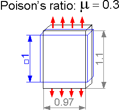 Poisson's ratio m characterizes transverse deformation under axial tension or compression. It is a dimensionless parameter. For m=0.3, axial tension of 10% corresponds to a transverse compression of 3%.

 The expressions show another form of the Hooke's law. Normal stress sx depends on all three linear components of strain ex, ey and ez.
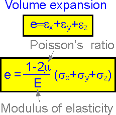 Volume expansion e characterizes an increase of an element size, not a change of its shape. It depends on the linear strains only. The volume expansion e can be defined by the elastic constants of the material E, m and the sum of the normal stresses sx, sy and sy.
PLANE PROBLEMS
 There are two special states of stress: plane stress for thin plates and plane strain for thick plates.
For plane stress there are four non-zero strain components (ex , ey , ez , gxy ) and three non-zero stress components (sx , sy , txy ). The plane stress is typical for thin-walled structures such as in airplane wings.
For plane strain there are three non-zero strain components (ex, ey, gxy) and four non-zero stress components (sx, sy, sz, txy). Plane strain is typical for thick plates.
 There are two equilibrium equations that must be satisfied for absence of mass forces. Elastic plates have stress fields that satisfy Hooke's law and the strain compatibility equations. The two stress components shown correspond to an embedded beam with a force applied to the right end. The equilibrium equations help solve the plane problems of the theory of elasticity.
 There are two inclined principle planes where there is no shear stress and normal stresses (s1 and s2) are at a maximum.
 Principle axes are inclined 45o to the direction of shear stress t for pure shear. Indication A is negative. There are zero indications for B and D.
 The figure shows typical stress patterns for sx, sy and txy. The normal stress sx is usually higher than other stress components for a long beam, where Length >> Height.
 There is concentration of shear stress in the area where force is applied. Shear stress is equal to zero at the surface and is at a maximum in a neighboring region.
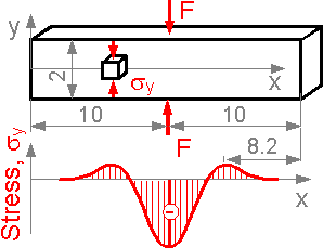 Normal stress sy at axis x can be positive outside the zone of compression. Here, the compressive stress is significantly higher than the tensile stress.
 Saint-Venant's principle. At a distance equal to width of the beam (2a), the maximum stress does not exceed the nominal stress by 4%. The stress pattern becomes practically uniform.
TORSION
 Torsion is related to shear stress. Only two shear stresses are nonzero at planes perpendicular to the shaft axis. All other stress components including all normal stresses in the chosen coordinate axes are equal to zero.
There is no tensile strain in the vertical or horizontal directions for pure shear (torsion). There are no readings on the two strain gauges shown.
 The figure shows the results of a finite element analysis for a prismatic bar under torsion. The shear deformation is at a maximum in the center of the bar. The shape of the square mesh at the surface of the bar changes. The height of the rhombus and its area become smaller. This means that the bar becomes a little shorter.
 The figure shows four specimens with equal cross sections. The thin-walled example A demonstrates the smallest torsional rigidity.
The specimens are shown in increasing order of the torsional rigidity.
Deplanation of a plane section is the out-of-plane deformation of its points. For all examples except cylinder D there is deplanation.
 Shear stress is doubled near the small keyslot. The stress concentration factor is equal to 2 for the small keyslot.
There is stress concentration near the diameter change. The stress concentration factor depends on radius of curvature.
 The formula defines maximum shear stress for a rectangular section. The maximum shear stress acts at the middle of the longer edge of the rectangle. The coefficient k grows from 0.208 at b/a=1 to 0.333 at infinity.

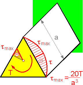 Maximum shear stress in the middle of a side of a triangle is inversely proportional to a3. The shear stress is equal to zero in the corners and center.
 For thin-walled symetrical sections the shear stress is approximately zero in the inner wall. All shear stresses tend toward the "external circle".
BENDING
 There are shear and tensile stresses in bending beams. Usually the beams fail due to bending tensile stress. An exception is beams with high h/L ratio. A height increase results in an increase in the tmax/smax ratio.
The shear stress is at a maximum and there is no tensile bending stress at the neutral line of a bending beam. The maximum tensile stress act at the upper or lower segments of the beam.
The principle planes are planes where there are no shear stresses and the normal stresses are at a maximum. The principle axes are inclined by 45o to the neutral axis. The principle axes coincide with the coordinate axes at the upper and lower sections of a bending beam.
 The neutral line is shifted to the center for a curved beam. The absolute value of the maximum compressive stress is smaller than that for tension for the shown loading condition. For R/h > 20 the stress field can be considered the same as for a straight beam.
 The maximum shear stress depends on the transverse force F, the cross-sectional area A and Poisson's ratio m. The shear stress is at a maximum in the center of the section. The bigger the distance from the neutral axis, the bigger the bending tensile stress.
 There is a stress concentration in the bending beam. The stress concentration factor depends on the ratio of the radius of curvature to the decreased height of the beam.
 The figure shows a curved central line of the beam. The angle of rotation is at a maximum at the right edge of the beam.
 Shear stress can result in torsion of non-symmetrical sections. Applying force at a distance e=0.548r does not cause torsion of the beam with a half-round cross section.
POLAR COORDINATES
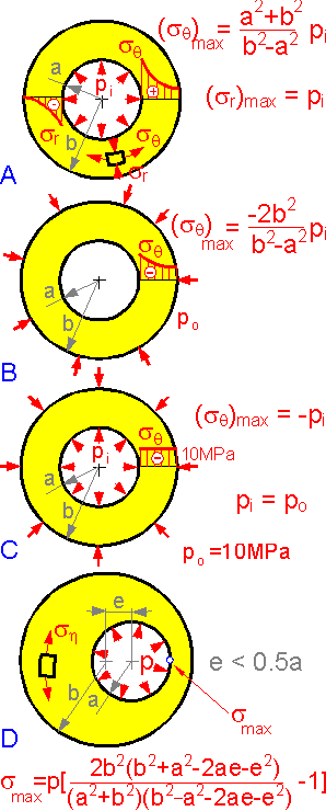 There are tangential sq and radial sr stress components in polar coordinates. The coordinates are used for round elastic bodies. The tangential tensile stress is at a maximum at the inner surfaces of a cylindrical tube with inner pressure pi, A.
The tangential stress is negative for external pressure B.
There is no stress gradient if the external and inner pressures are equal, C.
The eccentricity e increases the maximum tensile stress at inner surface, D.
 There is a stress concentration near the round hole in the plate. The stress concentration factor is equal to the ratio of the maximum to the nominal stress. Stress concentration factor is 3.0 for point 2 . Stress sy is negative for point 1. Compression is similar to tension, merely change the signs.
For the complex loading shown here, the tangential stress sq is at a maximum in the horizontal section due to the effect of "tension + bending + stress concentration".
 Stress concentration is higher for an elliptical hole under tension than for a round hole.
For pure shear the absolute value of normal stress is highest at a point between A and C. For a round hole (a=b) the stress concentration factor is equal to 4 for pure shear.
The stress pattern is linear for bending except near the elliptical hole where stress increases.
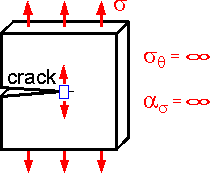 The theoretical stress concentration factor for an ideal elastic body is equal to infinity in the crack tip. Infinite stress is not seen in actual materials due to plasticity and finite microstructure.
 The tangential stress is equal to the radial stress for this loading scheme. The stress depends on angle q, not on the radius r. The smaller the angle q, the larger the absolute value sq. The stress is equal to distributed load q at the surface (q=0).
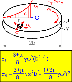 A rotating disk: g is the density of material, m is Poisson's ratio, w is the rotation speed.
The radial stress is higher than the tangential stress. It is proportional to the squared rotation speed and highest in the center.
PLATES
 Bending is the most important loading situation for thin plates. Bending moment depends on bending rigidity D of the plate and the shape of the deformed plate (deflection and its derivatives). The bigger the thickness h, the bigger the bending rigidity D and the absolute value of the bending moment. Maximum bending stress is proportional to bending moment M and inversely proportional to h3.
There is usually bending relative to both axes x and y. For the shown embedded thin plate, upper layers are under compression and lower layers are under tension in the center of the plate.
Both normal stress components sx and sy are at a maximum at the lower surface of the plate.
 The maximum deflection for a round simply supported plate with a force in the center is proportional to (a/h)2.
The maximum stress and deflection depend on the support method. The more rigid support, the smaller the maximum bending stress smax and maximum deflection of the round plate.
 The plate shown here is loaded with evenly distributed forces. The maximum deflection in the center the of plate is inversely proportional to h3. Cutting the thickness h in half increases the deflection by 8 times.
For a rectangular plate with a force in the center, the bending stress is at a maximum in the middle of the longer side.
 The stress concentration factor as is smaller for bending of thin plate than for tension of a plate (as=3.0). The stress concentration factor for bending depends on Poisson's ratio m. It is approximately equal to 1.8 for steel (m=0.3).
 The upper surface of the plate was rapidly heated to 100oC. This causes thermal bending stress in the plate. The thermal stress depends on the difference in temperatures, thermal expansion coefficient and elastic constants of the material. The thermal stress does not depends on the thickness h.
SHELLS
 The tangential stress is equal to meridian stress for spherical shells. Radial displacement (radius increase) is directly proportional to the inner pressure and R2. The bigger the Young's modulus of the material, the smaller the displacement.
 The tangential stress for a cylindrical pressure vessel is twice as large as the meridian stress.
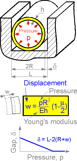 The radial displacement is proportional to pressure. The bigger the displacement, the smaller the gap between the cylindrical vessel and the wall. There is a pressure when the gap is zero.
 Tension in the X-direction results in deformation in the vertical direction. This theory gives the formula for calculation of the displacement dy.
 A cylindrical shell is compressed. The figure shows patterns of deflection w, angle of rotation q, bending moment M and transverse force Q.
 The bending moment and bending stress are at a maximum at the bottom of the tank. The most effective use of material utilizes thicker parts at the bottom.
 The tangential and radial stresses are at a maximum in the bottom of the water tank. There is a quadratic dependence of the stress on the radius of the half-sphere R.
 If a spherical dome accepts its own weight, the increase in thickness h results in an increase of the shell weight and its bending rigidity. The two factors compensate for each other. Therefore, maximum stress does not depend on thickness of the shell.
 A thin-walled cylindrical ring can lose its shape due to a pressure increase. The more rigid the material, the bigger the critical stress. Critical pressure is proportional to Young's modulus E.
 A thin wall cylindrical shell can lose stability at shear stress tcritical. Geometrical parameters have different effects on the critical stress. Length L has no effect on the critical stress tcritical. The bigger the radius R, the smaller the stress. The bigger the thickness h, the bigger the critical stress tcritical.
CONTACT STRESSES
 The shape of the contact area between two elastic bodies is usually circular, elliptical or rectangular. This is valid for ideal elastic bodies.
 The size of the contact area depends on the modulus of elasticity of the balls, their radii and the compressive force F. It is proportional to F1/3. Absolute value of the contact normal stress s3 is at a maximum at the contact surface. The two other components are 80% of s3. Maximum shear stress acts inside the ball at 0.4a from the surface.
 For compression of two balls the contact stress is at a maximum in the center of the contact spot. The stress decreases to zero at the edges of the contact region. For the two other loading situations, the stress is not the highest in the center.
The theory of elasticity predicts the maximum contact stress for ball bearings. The smaller contact stress, the better. The smaller the modulus of elasticity E, the smaller the contact stress. The hardness, not the contact stress, is more important in choosing the material for ball bearings.
 Shear stress in a rail is approximately equal to zero at the surface (z=0) and is at a maximum at a distance 0.45a from the contact zone, where a is size of contact region.
 The distance between the centers of the cylinders decreases with an increase in force. There is no linear dependence for the elastic displacement D.
 Time of contact for impact between two steel balls in a ball mill is proportional to the radius of the balls R. Increase in the modulus of elasticity or in velocity decreases the time of contact.
The bigger the size of the balls the longer the time of contact.
REFERENCES
S.P. Timoshenko, J.N. Goodier Theory of Elasticity, McGraw-Hill, N. Y., 1970.
S.P. Timoshenko, S. Woinowsky-Krieger Theory of Plates and Shells, McGraw-Hill, N. Y., 1959.
THEMES
Theme 1. Stress Concentration
Theme 2. Fracure Mechanics
Theme 3. Mechanical Properties
Theme 4. Strength of Materials
Theme 5. Theory of Elasticity
Theme 6. Structural Safety
Theme 7. Material Science
Theme 8. Welds
Theme 9.Composite Materials
Theme 10. Finite Element Analysis
STRUCTURAL SAFETY
Igor Kokcharov and Anatolii Lepikhin
RELIABILITY
Dependability is the ability of a structure to maintain its working parameters in given ranges for a stated period of time. Dependability is a collective term used to describe the availability performance and its influencing factors: reliability performance, maintainability performance and maintenance-support performance. Dependability is used only for general descriptions in non-quantitative terms.
Maintainability is a measure of the ease and rapidity with which a system can be restored to operational status following a failure.
 Reliability is the probability of component or system success under stated conditions for a stated period of time. Time to the moment when the structure fails is not exactly known. The time is a random variable. Reliability is characterized by the reliability function R(t):
R(t) = P{t > t}
where P is the probability that the operating time to failure t exceeds the stated period of time t. Probabilities are numbers between 0 and 1.
The reliability function is related to the probability of failure function F(t) and its density function f(t):
F(t) = 1 - R(t) ; f(t) = d F(t) / dt = - d R(t) / dt;
The domain of the cumulative distribution function F(t) is from zero to infinity, while its range is the interval [0 ... 1].
 Failure rate l(t) is an important parameter of reliability.
Every random variable has its associated cumulative distribution function. The cumulative distribution function F(t) is increasing (accumulating probability) as t increases.
If the failure rate is constant (exponential law of reliability) the dependence between failure rate and reliability function can be simplified.
 Statistical estimators of the function can be obtained by the following expressions.
Here:
n(t) - number of failed elements to time t.
N - total number of elements.
to - mean time to failure.
 There is some standard behavior of the dependence curve of failure rate l versus time t:
1. failures due to manufacturing defects (cracks, inappropriate materials, poor design)
2. failures due to conditions of service (exploitation errors)
3. failures due to accumulated damage (wear and fatigue)
 The figure shows typical ranges of failure rate for different engineering systems. The parameter changes over a wide range.
|
из
5.00
|
Обсуждение в статье: THREE-DIMENSIONAL STRUCTURES |
|
Обсуждений еще не было, будьте первым... ↓↓↓ |

Почему 1285321 студент выбрали МегаОбучалку...
Система поиска информации
Мобильная версия сайта
Удобная навигация
Нет шокирующей рекламы

