 |
Главная |


CORROSION OF METALS AND ALLOYS
|
из
5.00
|
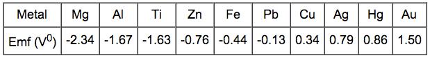
The electrochemical series ranks the general resistance of metals to corrosion. The more negative the standard Emf (Electromotive force) potential, the more easily the material will oxidize.
The monocrystal structure shows a higher resistance to corrosion than the same metal with polycrystalline structure. The smaller the size of grains, the more the material is prone to corrosion damages.
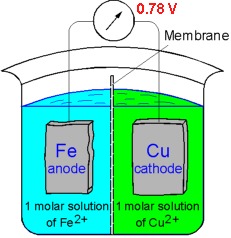 If two metals are electrically connected and immersed in a solution of their own ions the EMF potential determines which material will corrode. Iron dissolves in the electrolyte because iron has electrode potential (-0.44 V) lower than that of copper (0.33 V). Consquently, the copper deposits on the cathode. The magnitude of the voltage driving the dissolution of iron is found to be:
DV = V1 - V2 = 0.34 - (-0.44) = 0.78 V
 Galvanic corrosion occurs when dissimilar metals are placed in assembly within a corrosive electrolyte (e.g. sea water). This results in one of the metals becoming anodic and corroding at faster rate than normal. The other metal is the cathode responds with a decrease in corrosion rate. The Galvanic series is useful for selecting materials to be joined. Materials towards the bottom of the table are more active (anodic) and will corrode at a faster rate than those above them. In addition, the closer two metals are in the table the weaker the corroding effect.
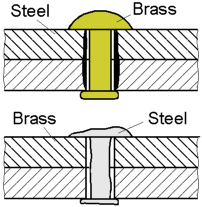 Corrosion rate depends on the relative areas of the anode and cathode. When the surface area of the anodic metal is smaller than that of the cathode the resulting corrosion is rapid. Consequently, the corrosion rate is slow when a larger anode is connected to a small cathode.
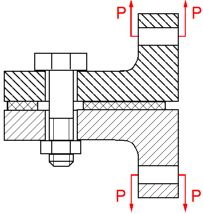 The bolt displayed under a constant load will corrode at a greater rate than one that is unloaded. This is due to regions of a high local stress being anodic to those of a lower stress. The combined action of a sufficient applied tensile stress and an aggressive environment can cause the cracking of a part.
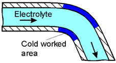 Areas of metals subjected to cold working are rich in dislocations and therefore constantly under stress. This results in them being anodic to the less stressed regions and accelerates corrosion.
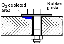 The flow of oxygen to the area under the gasket is restricted and therefore its concentration is low. This area will be anodic and corrode faster than the oxygen rich areas.
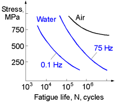 For a given fatigue life the influence of a corrosive environment on the fatigue strength of metals increases if the frequency decreases. This means that a structure loaded at a lower frequency will sustain less cycles to fracture at a given applied stress. The picture shows S-N curves of carbon steel tested in several mediums. All metals and alloys cyclically loaded under a corrosive environment do not exhibit a endurance (fatigue) limit. Which means that a structure exploited under such conditions will finally break even if applied stress is very low.
CASTING
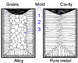 The typical structure of a cast alloy consists of three zones:
1. Chill zone - a few layers of fine equiaxed grains near the mold walls.
2. Columnar zone - oriented grains grown in the direction opposite of the heat transfer through the mold.
3. Equiaxed zone - equiaxed grains of large size at the center of the casting.
Depending on the processing conditions and material the proportion of the columnar and equiaxed zones can be altered. Slow cooling, adding the nucleating agents and agitating the melt contribute to the growth of equiaxed zone. The enlarged columnar zone is peculiar for pure metals.
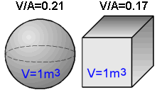 The greater the volume to surface area ratio, the slower a solid body cools and solidifies.
Solidification time can be estimated by Chvorinov's rule:
TS = B(V/A)2,
where V is the volume; A is the surface area; B is an empirical constant.
 Patterns very often have a temper on the vertical surfaces parallel to the direction of withdrawal. This allows for an easy removal of the pattern from the mold without any distortion or breaking of the mold cavity. The angle of draft is normally 0.5-2o. The angle depends mainly on the materials and processing conditions.
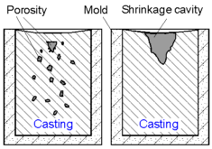 Materials with a short temperature range of crystallization (eg. pure metals or eutectic alloys) tend to form a large concentrated shrinkage cavity (right). The castings of alloys with a large freezing range have porosity dispersed in the bulk of the material (left).
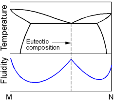 The fluidity is the capability of material to flow into mold cavities prior to solidification. The fluidity of pure metals and eutectic alloys is higher than that of hypoeutectoid or hypereutectoid alloys.
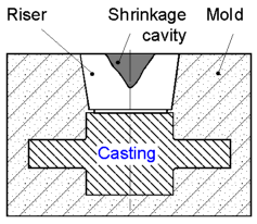 Risers are used to compensate for the shrinkage of molten metal during solidification and to avoid the formation of a shrinkage cavity within the casting. The shrinkage cavity forms into the riser because it is the last part solidified in the mold. The risers are usually located over the center of the heaviest sections of castings.
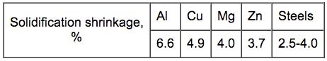
The riser must be large enough to feed the shrinkage in the casting.
Solidification shrinkage varies for different metals and influences the size of the risers.
Permanent mold casting vs Sand casting:
Increased dimensional accuracy and smoother surfaces;
A new mold to produce every part is avoided;
Increased mechanical properties due to a fine grain structure;
Less time to cast a part;
Shape and size of castings are limited;
Not suitable for metals with a low fluidity.
POLYMERS
 The molecular structure of polymers can be linear, branched, cross-linked or networked (highly cross-linked). Thermoplastics have either a linear or branched structure. Thermoplastics soften upon heating and harden when cooled, without ever changing the material properties. This permits the recycling of thermoplastic scraps. Cross-linked polymers are called thermosets. When heated a thermoset remains relatively hard and can not be reprocessed without chemical degradation.
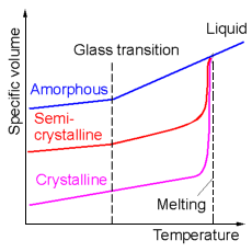 Crystalline materials exhibit a sharp change in the specific volume (inverse of density) at their melting temperature. The density of pure amorphous materials changes at the glass transition temperature. This entails significant changes in mechanical properties. Generally below this temperature polymers are stiff and brittle, while above it they act flexible and ductile. Semicrystalline polymers exhibit an intermediate behavior which includes a defined melting temperature and slight change in density at the glass transition temperature. For thermoplastics and thermosets the glass transition temperature is above the ambient temperature while for elastomers the glass transition temperature is below room temperature. Elastomers can undergo large deformation (up to several hundred percent) and recover in shape and size upon removal of the load.
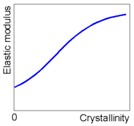 A slow cooling rate results in a high degree of crystallinity for semicrystalline polymers. The degree of crystallinity influences mechanical properties. The elastic modulus of the crystalline phase is sufficiently higher than that of the amorphous phase. In general, the higher crystallinity, the higher the elastic modulus and strength of the material.
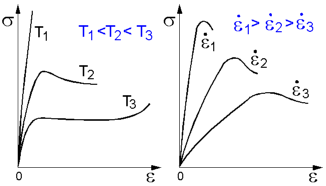 Mechanical properties of thermoplastic polymers strongly depend on the test temperature and strain rate. The polymer becomes softer and more ductile with increasing temperature. In general, strain rate decrease has the same effect on the stress-strain behavior as temperature increase.
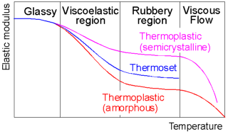 The effect of temperature on the mechanical behavior of polymers differs for thermoplastics and thermosets. Thermosets do not exhibit viscous flow. They are known to degrade and decompose at high temperature.
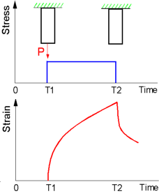 The viscoelastic behaviour is peculiar to amorphous polymers above the glass transition temperature. There is no immediate response in deformation on the applied stress. Viscoelastic deformation is a combination between the viscous deformation of liquid and elastic deformation of solid.
COMPOSITES
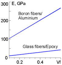 The modulus of an unidirectional composite along the fiber direction can be calculated by the rule of mixtures:
Ec = EfVf + EmVm,
where Ef - the modulus of the fiber; Em - is the modulus of the matrix; Vf , Vm - the volume fraction occupied by the fibers and the matrix respectively.
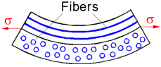 A cross-ply composite laminate [0o/90o], shown at the right, will warp under uniaxial tensile stress due to the difference in stiffness along and perpendicular to the fiber axis. The stiffness along the fiber axis is greater and therefore the ply with fibers parallel to the applied stress will be stretched less than the ply loaded across the fibers.
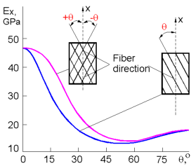 The elastic modulus of continuous fiber composites strongly depends on the angle between the fiber direction and the applied load. The maximum stiffness of the composite is achieved when the applied load is parallel to the fiber direction. The stiffness of cross-ply composites [+q/-q] is greater than that of the unidirectional composite due to additional restraint to shear deformation.
 The greater the volume fraction Vf of fibrous unidirectional composites the higher their capability to sustain cyclic loading. The resistance to fatigue of composites strongly depends on the angle q between the direction of applied loading and the fiber axis. The fatigue strength decreases when the angle increases.
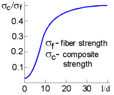 Composites with short fibers display a greater strength with an increase in the ratio of fiber length to diameter l/d. As the number of defects decreases along with the fiber diameter the strength increases. Additionally, for the same volume fraction the longer fibers can support a greater portion of the load transferred from the matrix.
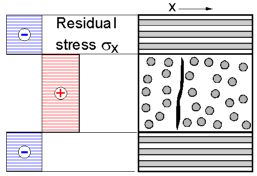 Residual stresses are developed during the cooling of cross ply composite laminates due to anisotropy of thermal contraction parallel and perpendicular to the fiber direction. In glass fibers/epoxy composites the thermal expansion coefficient along the fiber direction is greater than that perpendicular to the fibers. Following the cooling the plies of 90o are in tension and the plies of 0o are in compression. Generally, cracks are formed perpendicularly to the tensile stress.
 Composites are known to have a large specific strength, which is defined as the ratio of the ultimate tensile strength suts to the weight rg.
Specific strength of continuous fibers composites is much greater than that of such conventional materials as aluminium or steel.
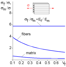
 The load applied to a fiber composite is supported by both the fibers and matrix. The relationship between the load carried by fibers Pf and matrix Pm depends on the ratio EfVf to EmVm:
Pf / Pm = EfVf / EmVm ,
where Ef, Em, Vf and Vm represent the elastic modulus and the volume fraction of the composite components. The higher the elastic modulus and the volume fraction, the greater portion of the applied load is carried by the fibers.
 Assuming no slip between the fibers and matrix the stress acting on the composite is determined by the following:
s = sfVf + smVm
where Vf and Vf - the volume fraction of the fibers and matrix respectively.
The stress in the matrix
sm = sf x Em/Ef .
The stress in the fibers:
sf = s / [Vf + (1-Vf) x Em/Ef] .
Assuming a constant applied stress, the greater the volume fraction of the fibers the less they are stressed.
FORMING OF METALS
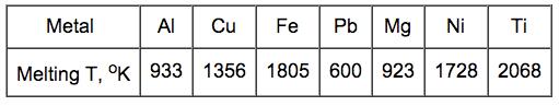
Hot working is a process in which a metal, above its recrystallization temperature, is deformed and strain hardening does not occur. Normally, hot working refers to procedures performed at temperatures of 0.5-0.75Tmelting (in oK). It should be noted that the forming of lead at room temperature can be considered a hot working process because of lead's low melting temperature.
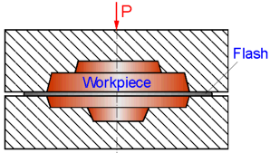 Flash is formed when a minute amount of a metal flows outside the die during hot forging. The flash cools faster than the bulk of the workpiece because it is much less thick. This increases the resistance of the flash to deformation and forces the bulk to flow inside the die cavities.
Features of Cold Working vs. Hot Working
Better surface finish.
Increased dimensional control due to elimination of shrinkage during cooling.
Strength and wear properties of metal parts are higher while keeping the ductility lower.
Large deformation results in a greater tensile and yield strength along with a lower ductility.
Directional properties of metal parts can be formed.
Less contamination problems.
More powerful equipment is needed.
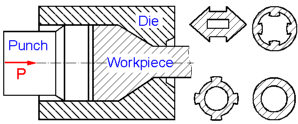 Extrusion is used to produce solid or hollow parts with long lengths of constant cross-section. Extruded products include both simple as well as complicated cross sections (eg. internal ribs) that can not be produced by any other techniques of material forming.
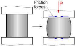 Friction between the contact surfaces is known to cause uneven compression of the deforming materials upon upsetting. This results in the barreling of the workpiece.
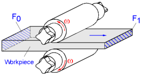 The length of the rolled workpiece is increased proportionally to the decrease of its cross sectional area. During rolling the volume of the material remains constant:
F0 l0 = F1 l1,
where F0, F1 - the cross sectional area before and after rolling respectively; l0, l1 - initial and final length of the workpiece.
Hence: l1 = l0 F0/F1
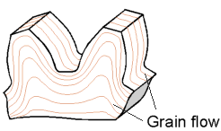 Forging refines the grain structure and improves the physical properties of the metal. Grain flow is defined as the direction of the pattern that the crystals take during plastic deformation. The grain flow can be oriented in the direction of principal stresses encountered by the piece.
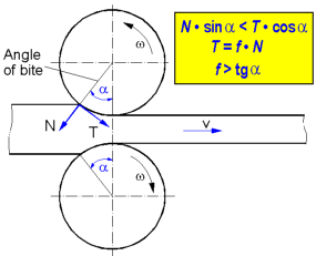 The figure on the right dispays the forces acting on a workpiece from the rolls at the point of contact. Where N - normal force; T = f N - friction force; f - the coefficient of friction.
The workpiece will be drawn forward if
N sin(a) < T sin(a) or f > tg(a)
where a - the angle of bite.
If friction between the contacting surfaces decreases the maximal possible angle of bite is reduced.
REFERENCES
W.D. Callister Jr, Materials Science & Engineering, An Introduction, Wiley, 5th edition, 1999.
W.F.Smith.Principles of Materials Science and Engineering, 2nd edition, McGraw Hill, 1990.
THEMES
Theme 1. Stress Concentration
Theme 2. Fracure Mechanics
Theme 3. Mechanical Properties
Theme 4. Strength of Materials
Theme 5. Theory of Elasticity
Theme 6. Structural Safety
Theme 7. Material Science
Theme 8. Welds
Theme 9.Composite Materials
Theme 10. Finite Element Analysis
WELDS
Igor Kokcharov and Anatolii Lepikhin
WELDED JOINTS
 Welding is a method of joining two parts by melting and/or pressing them together.
Welds are permanent joints of metals (iron, steels, aluminum alloys, titanium alloys) or plastic materials.
Aluminum and steel cannot be melted together since they have different melting points (temperatures).
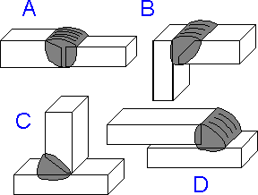 There are the following types of welds:
A. butt-weld
B. corner weld
C. T-weld
D. lap weld
 Static and fatigue strength is highest for a lap-weld in comparison with other joints from the list.
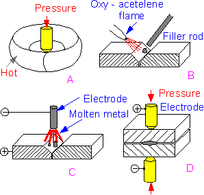
n forge welding, A, for steel chain manufacturing, two parts are heated and then hammered together.
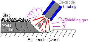
Gas welding, B, uses an oxy-acetylene flame to heat the metal and a rod of metallic filler material.
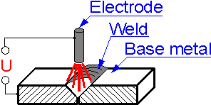
In electric-arc welding, C the filler rod forms one electrode and the metal itself another. Electric current passes across the gap between the electrodes by arcing or sparking and melts the surfaces together. The electric current (ac or dc, alternating current or direct current) is stable with an amperage of 150 - 500 Amperes. Industrial power sources usually work with voltages between 22 - 36 Volts.
Contrary to gas welding, electric-arc welding is used for thick pieces of metal and high temperature.
If an electric current passes through two metal surfaces in close contact the temperature rises and melts the surfaces together known as spot welding or seam welding, D. This method is used in mass production.
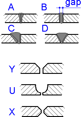 There are the following types of butt-welds:
A. without a gap
B. with a gap
C. with one-sided bevel
D. with two-sided bevel
A butt-weld without a gap is used if there is a guarantee of full melting. A butt-weld with a gap is used for thin-walled structures.
Edge preparation guarantees full melting and improved quality of the joint. There are Y-, U- and X-shaped edge preparation. U-shaped edge preparation is used instead of X-shaped edge preparation for thick parts if it is not possible to weld from two sides. Joints can be welded in a single pass or by few passes.
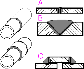 Weld joining of thick tubes also involves edge preparation, B in contrary to thin-walled tubes, A. Additional casing, C can be used.
Welds with a В«smoothВ» transition correspond to a stronger structure.
A great deal of skill is required to produce a reliable weld.
 Arc heat is expended during the melting of metal electrodes as it is in the heating of base parts. Approximate values of arc heat expended in shielded metal-arc welding:
A. Dissipation into the neighboring environment - 20%
B. Transition with molten drops - 26%
C. Vaporization of electrode metal - 24%
D. Absorption by base metal - 30%
MECHANICAL PROPERTIES
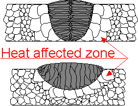 Mechanical properties are directly related to the material structure of weld and base metal. Weld metal is comprised of the metals of electrode and molten edges of base parts. High temperature affects the structure of base metal. Grain size enlarges at boundaries of the weld joint - in the heat affected zone (HAZ). Large grains have relatively poor mechanical properties. Outside the HAZ grain size is the same as in the base metal.
In molten weld metal the grains grow from colder parts of base metal.
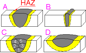 Lower amounts of molten metal correspond to lower heat and smaller HAZ. HAZ is smaller for electron beam welding:
A. Arc welding, butt-joint
B. Electron beam welding, butt-joint
C. Multi-layer arc welding, butt-joint
D. Gas welding, build-up weld
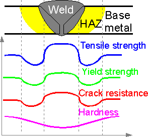 For steel welds mechanical properties are usually highest at the weld. The hardness is lower in the weld.
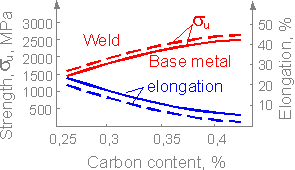 Mechanical properties of a high-strength steel weld depend on carbon content in the material. Increase in strength corresponds to decrease in ductility (elongation is a measure of ductility).
 Fast cooling, similar to quenching, could result in strength increase. Yield strength and ultimate tensile strength increase with higher cooling rate.
 There are special tests for weld joints. The welded specimen is tested until a crack first starts. The weld is stronger if it lies for a long time before a test.
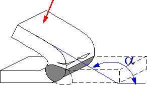 A large angle a characterizes the ductility of the weld joint. There are welded joints for which the angle could reach 180o.
STRESS CONCENTRATION
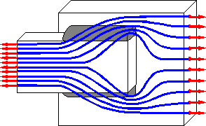 Passing through welds, inner forces meet obstacles on their path. They concentrate at the ends of weld. The force lines bend smoothly as they pass through the welds, lines cannot bend sharply.
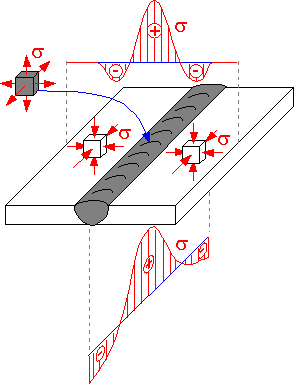
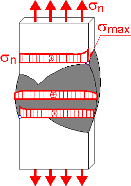 The figure shows a stress profile in the butt-weld. There is stress concentration in corners. Stress in the wider central section of weld doesn't exceed the nominal value.
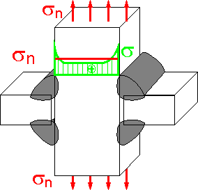 This stress pattern is typical for a welded joint. Sum of the area (force) under the curve must be equal to the sum of the area under the line corresponding to nominal value.
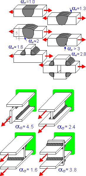
 Nominal shear stress is twice as large as the shorter welds. Stress concentration is higher if rigidities of connected parts are different. Stress is higher in the beginning of the short weld.
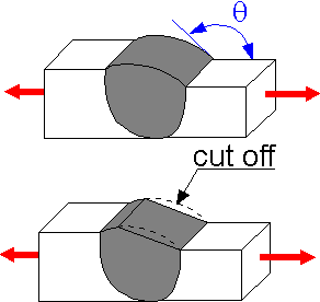 Stress concentration depends on the surface shape, not inside geometry of the weld. The larger the angle q, the smaller the stress concentration factor. In order to fulfill these requirements, a special cutting operation is made. Fatigue strength of a machined joint is higher than the first one.
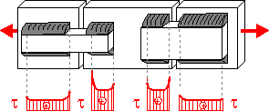
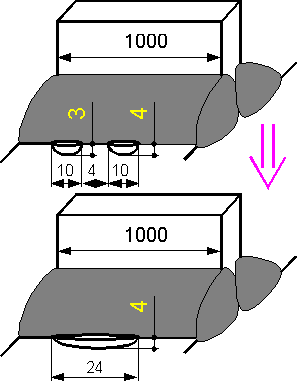
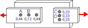 A large fraction of inner force goes through the end nugget in the row. The numbers indicate approximate values of the parameter.
 Stress concentration can be evaluated by stress concentration factor as which is equal to the ratio of maximum and nominal stresses.
DEFECTS
 The quality of weld depends on many factors:
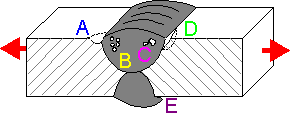
A. undercutting is caused by high amperage
B. porosity is caused by fast travel or dirty material surfaces
C. slag included in bead is caused by low amperage and short arc
D. lack of fusion is caused by low amperage and improper edge preparation
E. overlap is caused by electrode shaking
Surface defects perpendicular to tensile force are usually more dangerous than an inner defect of the same size. Lack of fusion, D is the sharpest and the most dangerous defect.
The quality of manual welding is usually less than that for other methods. Some imperfections that are not dangerous:
A. Electroslag welding: 0.56 defects / 10 meters.
B. Automated welding under flux: 2.5 defects / 10 meters.
C. Electric arc manual welding: 35 defects / 10 meters.
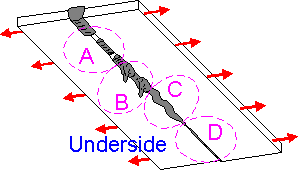 A. Incomplete penetration
B. Excess metal handing
C. Curved weld
D. Narrow weld at underside
Incomplete penetration means that tensile force lines meet obstacles on their path, causing high stress concentration. Other defects from the list do not cause high stress concentration.
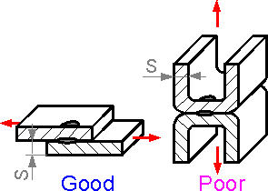
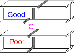
 Better melting takes place if there is a gap between the parts of Tee-weld. Residual stresses and cracking are smaller in this situation.
 A. Cracking: toe, longitudinal, transverse, and underbead cracks
B. Incomplete fusion
C. Undercutting and underfilling
D. Surface damage: small droplets and arc strike (electrode touch)
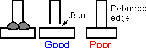
Cleaning the weld area prior ro welding improves the fusion of weld and base parts. The operation can guard against incomplete fusion, B.
A surface defect E in the heat-affected zone can be considered the most dangerous defect in the Tee-joint.
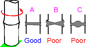
 Residual tensile stresses in the vertical plate is less than in the first instance. The second instance is poor for heavy welded construction, showing lack of ductility through the thickness of the material.
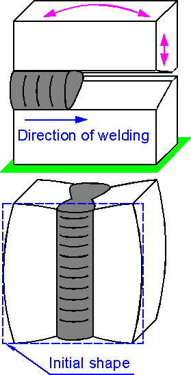
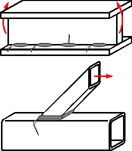
 Friction welding of steel bars. The bars are rotated relative to each other and squeezed together.
A. Uniform weld is preferential
B. High pressure or low speed
C. Low pressure or high speed
 Two defects can be considered as one if the distance between them is on the order of it's own size. The depth of the defect is more important than the length.
Residual Stress
 Unhomogenous heating causes local thermal expansion of metals. This is reflected in residual stress after cooling. Residual stress is a tensile stress in the center of a weld. Tensile stress in a weld is compensated by compressive stress in base metal.
 Weld metal is squeezed as it cools. During welding, edges move relative to each other, mostly perpendicular to the welding direction. Residual stress results in shrinkage of the structure.
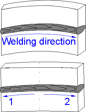 The choice of welding sequence affects the distortion of the welded structure. If a welder uses opposite directions, the distortion is smaller.
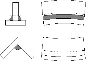 If a weld is below the neutral axis the shape is concave up. If a weld is over the neutral axis the shape is concave down.
 The angle b is small for small weld depths. The angle is not too large if the weld depth is equal to the thickness of the plate.
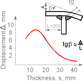 A similar effect can be observed in a tee-joint. For thin plates the displacement caused by residual stress is rather large, it decreases as thickness increases.
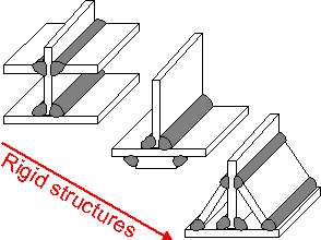 Residual stress is at a maximum for a rigid structure with a large number of welds and with closed loops. The structures are shown in order of increasing rigidity.
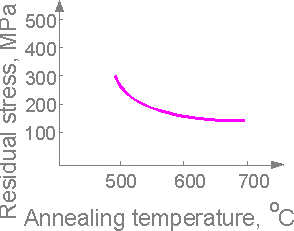 The residual stress decreases as annealing temperature increases. There are annealing procedures that can reduce residual stress to zero.
STRENGTH
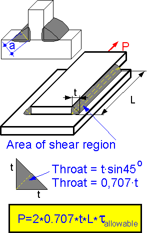 Strength of a welded joint depends on weld geometry and strength of materials. The minimum cross section of a weld is considered in strength calculations. Throat a is at a minimum. Throat is the distance from the root to the surface of a fillet weld. The throat of a fillet is a measure of the weld size. Critical force P for a lap joint using a 45 degree filet weld depends on allowable shear stress for the weld material tallowable.
 Bending stress is small if moment of inertia of the weld cross-section is large. The moment depends on the cross sectional area and it's distance from the neutral axis shown in the figure. The second example is three times stronger than the first.
The tensile strength of a butt-joint is higher for the case with low stress concentration. Build-up welds are often produced to increase wear resistance, not tensile strength.
 Spot resistance welding. The nugget is stronger under shear than in tension. Strength of nugget increases with thickness.
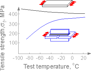 Contrary to uniform low-carbon steel plate, it's weld joint can have a brittle fracture mechanism: smaller critical stress at low temperature. Usually the temperature of brittle-ductile transition is below zero, ranging from -100oC to -40oC. Annealing increases the ductility of materials and prevents brittle fracture.
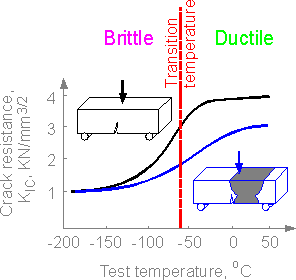 Crack resistance characteristic - the critical value of stress intensity factor depends on test temperature. Usually the brittle fracture for base metal, weld and heat-affected zone are similar, lower limits are equivalent. The characteristic of ductile fracture (upper limit) is usually smaller in the welded zone.
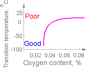 Presence of oxygen in weld material affects the embrittlement of the material. High oxygen content corresponds to embrittlement (relatively high transition temperature).
FATIGUE STRENGTH
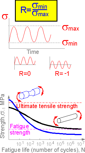 Fatigue strength is the strength of material under cyclic loading. It has unit of stress, [MPa]. Fatigue strength is usually two or more times less than ultimate tensile strength. Fatigue is characterized by fatigue strength sR, [MPa] and fatigue life N, [cycles]. R is cycle parameter, equal to the ratio of minimum and maximum stress.
During the initial cycles a notched ductile steel specimen can sustain stress exceeding the ultimate tensile stress. Fatigue strength at N=105 of notched specimen is usually lower than the unnotched.
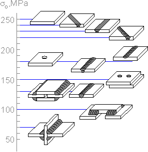 The figure shows approximate values of fatigue strength for carbon steel welded joints. The fatigue strength varies over a wide range.
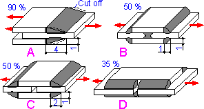 Geometry of weld affects the fatigue strength. A machined weld demonstrates greater fatigue strength. The numbers shows percentage of fatigue strength of a uniform plate under tension.
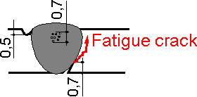 Fatigue cracks can start from all defects, but only one crack becomes dominate and results in failure. Lack of fusion on the surface is a case where the fatigue crack grows fastest.
 Initial manufacturing defects in welds decrease fatigue strength. The critical stress is sufficiently smaller than the static one.
 There are two main mechanisms of fatigue crack growth: I for small weld sizes s and II for large s. For large values of s the parameter does not affect the fatigue life of the joint.
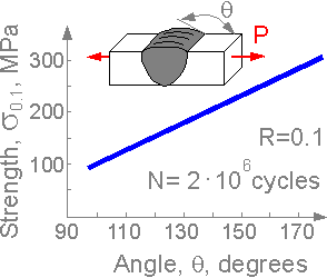 A large angle q corresponds to high fatigue strength. The effect of stress increase is higher for fatigue strength than for tensile strength.
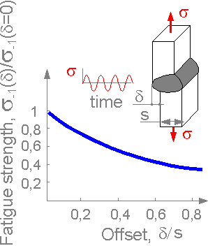 Imperfections such as offset d decreases fatigue strength of butt-welds. It creates high stress concentration, fatigue crack is initiated faster for a weld with an offset.
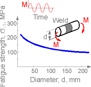 Fatigue strength decreases for greater cross-section due to larger number of surface defects and lower ability to deform plastically.
 Loading with negative cycle parameter R leads to increased local plastic deformation and faster crack initiation. Fatigue strength is lower at negative cycle parameter R.
FRACTURE
 There are three basic fractures connected with welded structures:
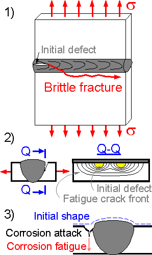
1) brittle fracture: fast crack propagated from a welding defect into a heat-affected zone, usually occurring within a second;
2) fatigue fracture: fatigue crack growing slowly from welding defects under cyclic loading;
3) corrosion fatigue: a crack propagated by joint action of corrosion (local embrittlement) and cyclic loading.
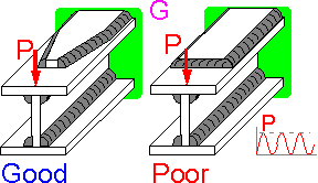
 For complex structures, the trajectory of a fatigue crack can be curved. A fatigue crack initiates from or tends to zones of maximum tensile stress. The strongest welded structures have the smallest concentration of welding defects and residual stress in the most highly loaded zones.
 Some welding defects can be observed at the weld surface. Defects in welds have different geometry and location:
A. Hot cracks are usually curved and open.
B. Cold cracks are usually straight.
C. Lamellar cracks are perpendicular to the thick plate surface.
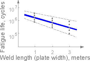 Scale effect. For wider welds there is a higher probability of weld defects and fatigue cracks. Fatigue life decreases with weld size increase.
WELDABILITY
 Weldability is the ability of materials (or structures) to form a strong defect-free weld. Poor weldability results in hot cracking, cold cracking or lack of fusion. Preliminary heating of base parts (preheating) decreases hot cracking. The best weldability can be obtained in the gravity position. Weldability depends on materials.
This list is in order of decreasing weldability:
Steel 0.2%C, cold-rolled
Stainless steel
Aluminum alloy 7075-T6
Ductile iron
The melting points of aluminum alloy and steel differ by more than 500 degrees Celsius. The metals cannot be melted together.
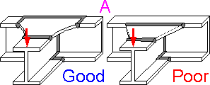
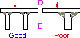
 To form a defect-free tee-joint it is better to use similar thickness of welded parts. An all-around welding of two massive (rigid) parts results in hot cracking.
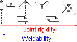 The more rigid a welded structure, the more susceptible to hot cracking. The specimens are shown in increasing order for susceptibility to hot cracking and decreasing order of weldability.
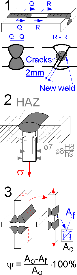 There are special tests to estimate weldability of materials:
1. Y-groove restrain cracking test for heavy plates with a new weld in the center. Hot cracking in the new weld is under investigation. This test helps to estimate susceptibility to hot cracking.
2.The implant method for studying weldability and determining susceptibility to cold cracking.
3.Tension of a machined specimen for studying susceptibility to lamellar cracking.
8.1
There are some simple rules how to design a reliable welded structure. We mention a few of them here:
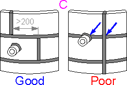
 A. Keep welds away from zones of high stress concentration.
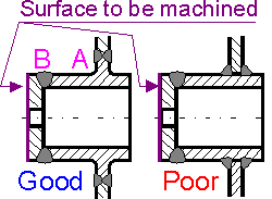 B. Keep welds away from surfaces to be machined.
 C. Don't make butt-weld intersections.
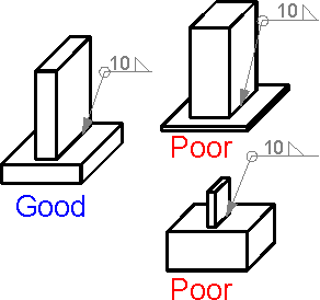
 D. Place vertical walls where force is applied.
 E. Choose proper weld size.
 F. Avoid gaps.
 G. Don't use sharp rigidity transition in tensile flange.
REFERENCES
Cary, H.B. Modern Welding Technology, Englewood Cliffs, N.J.: Prentice-Hall, 1979.
Gray, T.G.F., J. Spence, and T.H. North Rational Welding Design, New York : Butterworths, 1975.
Kalpakjian S. Manufacturing Engineering And Technology, Addison-Wesley Publishing Company, 1989.
Metals Handbook, 9th ed., Vol. 6: Welding, Brazing, and Soldering, Metals Park, Ohio: American Society for Metals, 1983.
Welding Handbook 8th ed., 3 vols, Maiami: American Welding Society, 1987.
THEMES
Theme 1. Stress Concentration
Theme 2. Fracure Mechanics
Theme 3. Mechanical Properties
Theme 4. Strength of Materials
Theme 5. Theory of Elasticity
Theme 6. Structural Safety
Theme 7. Material Science
Theme 8. Welds
Theme 9.Composite Materials
Theme 10. Finite Element Analysis
COMPOSITES
Igor Kokcharov
|
из
5.00
|
Обсуждение в статье: CORROSION OF METALS AND ALLOYS |
|
Обсуждений еще не было, будьте первым... ↓↓↓ |

Почему 1285321 студент выбрали МегаОбучалку...
Система поиска информации
Мобильная версия сайта
Удобная навигация
Нет шокирующей рекламы